


 53 / 365

© 2014 Foundation Supportworks
®
,
Inc.
All Rights Reserved
p 53
Chapter 2
Helical Foundation Systems
CHAPTER 2
HELICAL FOUNDATION SYSTEMS
• Align the drive head and product adaptor over
the extension shaft to allow for installation of
hitch pins or bolts.
• Advance the extension and any additional
extensions following the alignment adjustment
and coupling procedures described above.
Termination of Installation:
• Over the final 3 to 5 feet of installation,
assuming depth and minimum torque
requirements are being met, reduce rotational
speed to approximately 10 rpm. Provide
proper alignment and crowd.
Refer to the
Model Specifications for Helical Pile
Foundations in Appendix 2F for termination
criteria when the minimum overall length or
minimum torsional resistance is not met.
• Remove equipment from pile, establish top of
pile elevation and cut pile shaft to specified
elevation (if necessary).
• Install new construction bracket as specified
(Figure
2.12.3.1.b)
.
For
compression
applications, the new construction bracket
could technically be set on top of the pile
without bolting or welding. However, FSI feels
that it is good practice to provide positive
attachment of the bracket to the top of the pile
to prevent the bracket from being lifted off the
pile during concrete placement. Tack welds, a
single bolt, or use of compression-only plate
bracket assemblies are generally adequate for
this purpose. Where the top of pile has been cut
to achieve design elevation and tension loads
will be applied, bolt holes should be drilled
using drills and drill fixtures as recommended
by FSI to maintain bolt hole size, location and
spacing tolerances.
• Complete field installation logs.
Should field conditions present unanticipated
obstacles that require relocating of piles or
tiebacks, consult the engineer of record for
approval before proceeding.
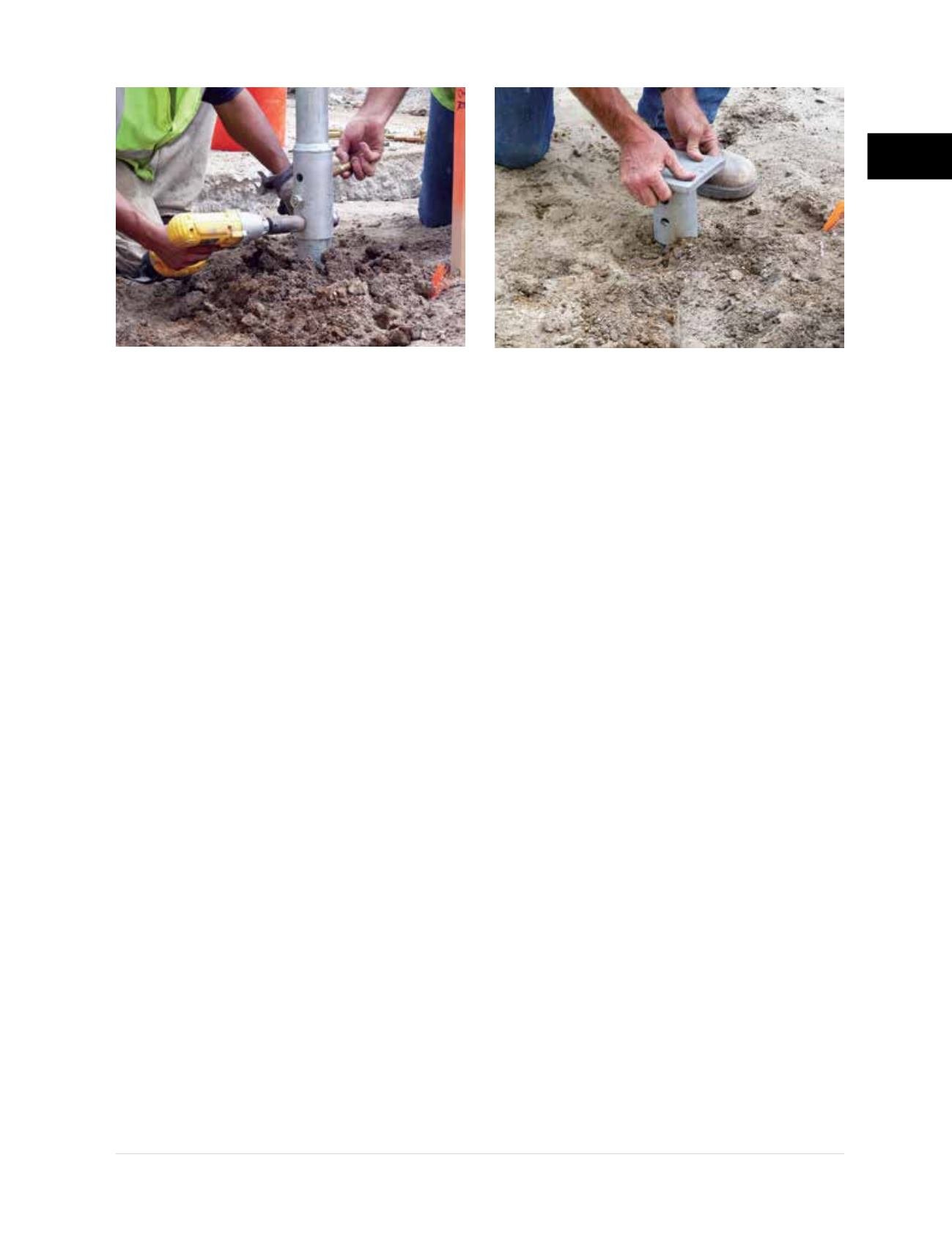
Figure 2.12.3.1.a
Install coupler bolts
Figure 2.12.3.1.b
Install new construction bracket