


 9 / 365

© 2014 Foundation Supportworks
®
,
Inc.
All Rights Reserved
p 9
Chapter 2
Helical Foundation Systems
CHAPTER 2
HELICAL FOUNDATION SYSTEMS
2.3.2 Central Shaft
The central shaft of a helical pile typically
consists of either solid square bar or hollow
round sections of tube or pipe. The shaft size
is selected to (1) resist the torsional forces
applied during installation and (2) transfer
the axial loads applied by the structure down
to the helix plates and surrounding soils. The
central shaft of an installed helical pile is
comprised of a lead section and extensions.
The lead section includes a 45-degree bevel
cut tip and one or more helix plates welded
along its length. The 45-degree bevel cut tip
further assists with pile advancement and
penetration through the soil. Lead sections are
generally fabricated in 5, 7 and 10-foot lengths.
Extensions, which may include additional helix
plates to provide increased pile capacity in
weaker soil conditions, are used to advance
the pile to the design depth, length, and/or
until the desired torque is achieved. Extensions
are generally fabricated in 3, 5, 7 and 10-foot
lengths. Custom lead and extension lengths
up to about 20 feet may also be considered
to reduce or eliminate coupled connections,
thereby minimizing overall product costs and
improving installation efficiencies. Generally,
a large track excavator would be required to
provide the reach necessary to install these
longer sections.
2.3.2.1 Coupler Detail
The coupler detail is yet another extremely
important feature when considering helical piles
and when selecting or specifying a product
manufacturer. Manufacturers may advertise
that they carry the same or equivalent helical
shaft. However, shaft and coupler details are
not consistent between manufacturers and
these differences may not be readily apparent
by simply reviewing marketing brochures and
product capacity tables. Some manufacturers
rate their products based upon the capacities
of the gross section of the shaft, thereby
ignoring any limitations caused by the coupled
connections. For these “equivalent” products,
there can be dramatic differences in material
properties, tolerances, spacing of bolt holes,
oversize of bolt holes, general fit-up, weld
quality, etc.
Some of the more common coupler details
for round shaft include external welded,
external detached, internal detached, and
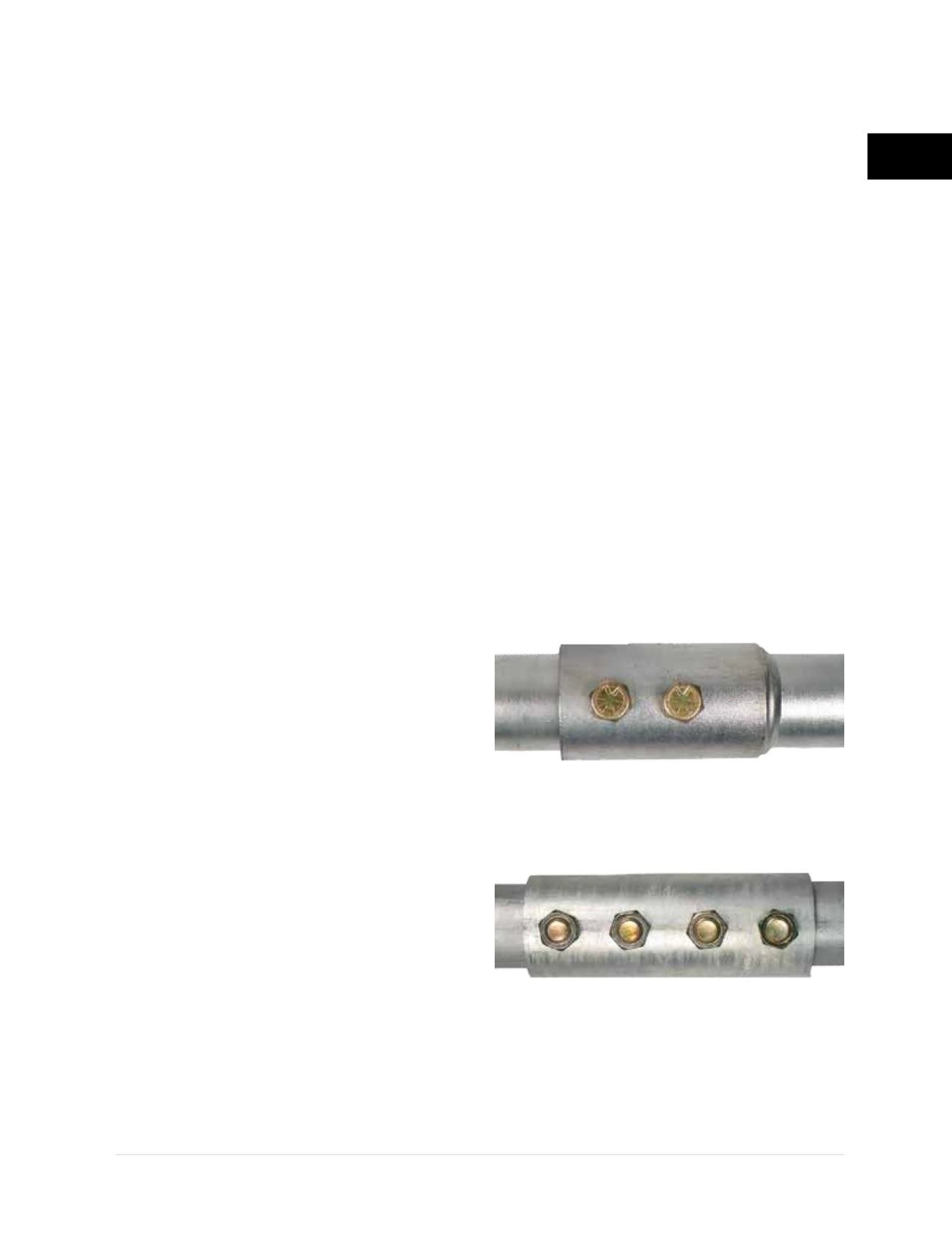
forged and upset. External couplers utilize
tube or pipe sections with an internal diameter
slightly larger than the outside diameter of the
central shaft material
(Figures 2.3.2.1.a1 and
2.3.2.1.a2)
. These couplers can be sized to
provide tight connections that reduce angular
deformation and variances from straightness.
Such displacements at the couplers introduce
eccentricities to the system which can
significantly reduce the allowable compressive
capacity of the pile, especially considering
the slenderness of the more widely used shaft
material (typically 3.5-inch outside diameter
and smaller).
Internal detached couplers are made from solid
round stock or tube or pipe material but with an
outside diameter smaller than the inside diameter
of the central shaft material
(Figure 2.3.2.1.b)
.
Figure 2.3.2.1.a1
FSI external welded coupler
Figure 2.3.2.1.a2
FSI external detached coupler