


 10 / 365

© 2014 Foundation Supportworks
®
,
Inc.
All Rights Reserved
p 10
Chapter 2
Helical Foundation Systems
CHAPTER 2
HELICAL FOUNDATION SYSTEMS
Internal coupler diameters may be significantly
undersized to prevent interferences with internal
weld beads of the central shaft or due to the
variations that are typical in wall thicknesses
and inside diameters of pipe sections. Larger
gaps between the inside diameter of the shaft
and the outside diameter of the coupler can
result in a connection with more potential for
angular displacements.
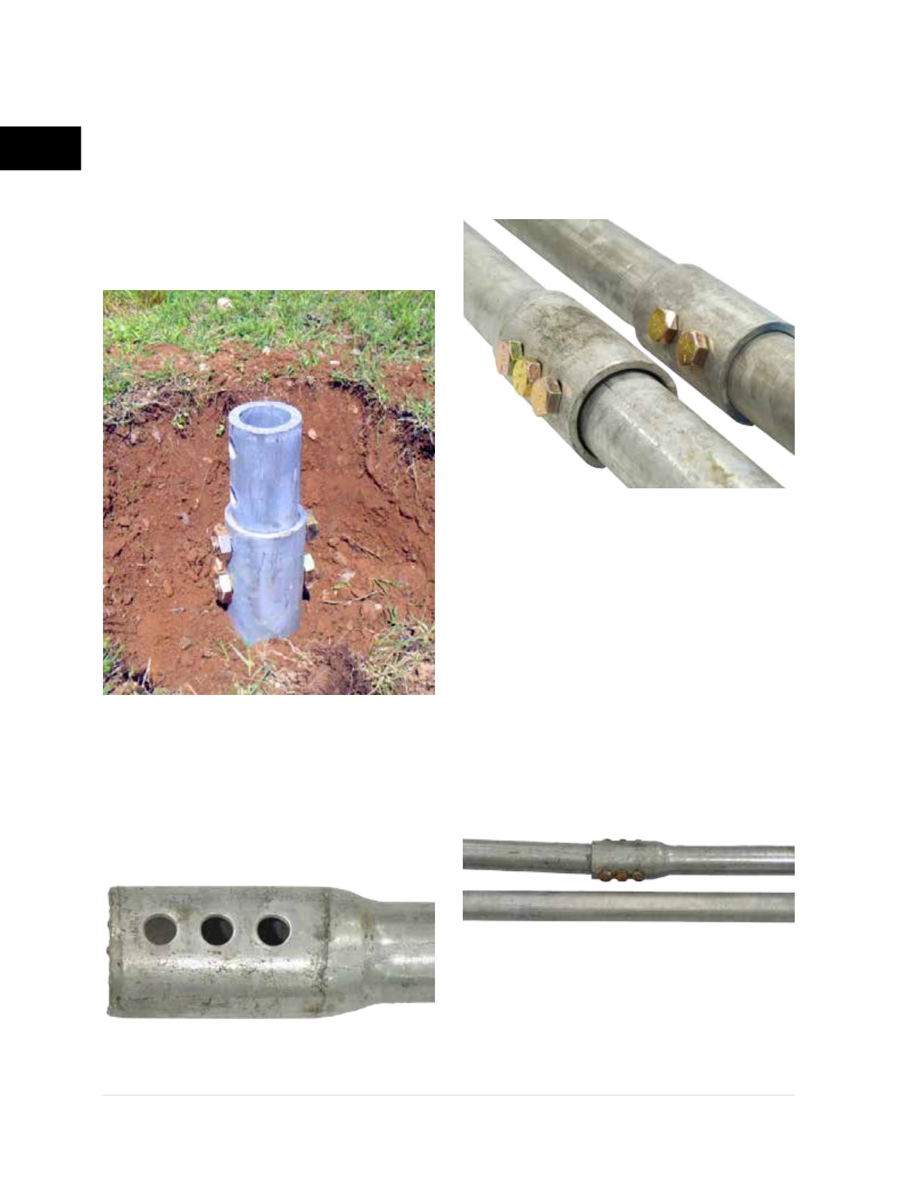
Forged and upset couplers are formed by heating
one end of the shaft, placing this end in a form
and then enlarging the end with a hammer-like
tool or press
(Figure 2.3.2.1.c)
.
With this method of manufacturing, it is difficult to
create tight connections to strict tolerances. It is
not uncommon to have
1/8
inch or more difference
between the outside diameter of the shaft and the
inside diameter of the upset coupler of the round
shaft
(Figure 2.3.2.1.d)
.
Again, the greater the freedom allowed in the
connection, the greater the potential variance
from straightness and the higher the potential
for bending or buckling of the pile under high
compressive loads
(Figure 2.3.2.1.e)
. The risk of
pile buckling further increases if the pile extends
through soil strata consisting of very soft clay
or very loose sand, or with unsupported pile
lengths through water, through fluid soils or
above the ground surface.
FSI round shaft helical piles are manufactured
with external welded, external detached or
internal detached couplers. Piles with shaft
Figure 2.3.2.1.c
Upset coupler with
oversized closely-spaced bolt holes
Figure 2.3.2.1.e
Competitor upset
coupler variance from straightness
Figure 2.3.2.1.d
Coupler tolerances; (A) Competitor
upset coupler, (B) FSI external welded coupler
A
B
Figure 2.3.2.1.b
Internal detached
coupler detail of FSI HP450