


 12 / 365

© 2014 Foundation Supportworks
®
,
Inc.
All Rights Reserved
p 12
Chapter 2
Helical Foundation Systems
CHAPTER 2
HELICAL FOUNDATION SYSTEMS
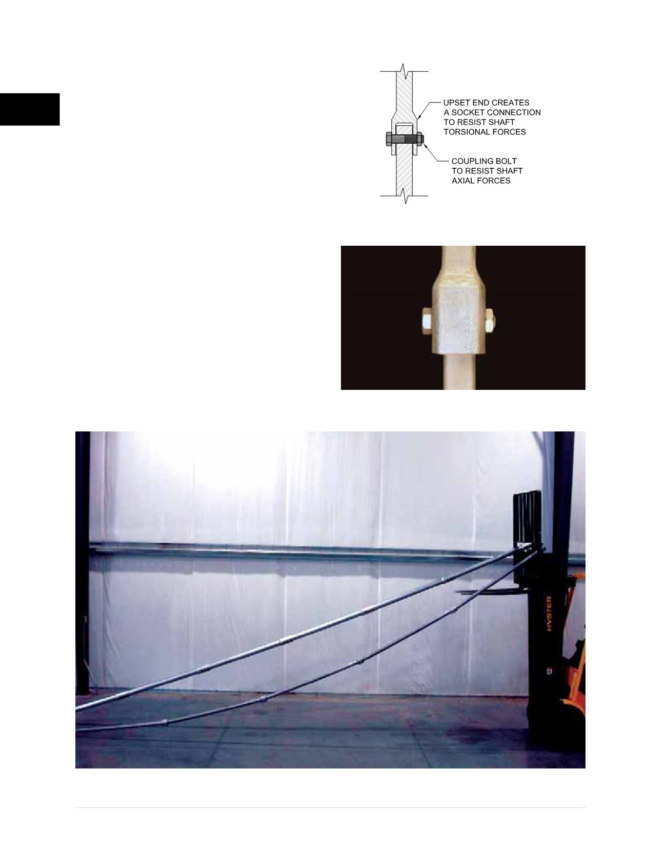
The most common coupler detail for solid
square shaft utilizes a forged and upset
end
(Figures 2.3.2.1.i1
and
2.3.2.1.i2)
. Cast
detached couplers and weldments have also
been used in lieu of the upsetting process.
The upset end of square shaft is created in a
similar manner as for the round shaft, except
for forming a square socket connection.
Figure 2.3.2.1.j
clearly shows a comparison of
coupling rigidity between an FSI external welder
coupler for round shaft and a typical upset coupler
for square shaft. A similar draping effect is typical
for round shaft helical piles with upset couplers.
FSI recommends that the design engineer
request product drawings and review coupling
details, tolerances and general fit-up prior to
product selection. As you have read in the
preceding paragraphs, seemingly equivalent
products may actually turn out to have very
different connection details, material properties
and capacities.
Figure 2.3.2.1.i1
Schematic of square
shaft forged and upset coupler
Figure 2.3.2.1.i2
Square shaft forged and upset coupler
Figure 2.3.2.1.j
Coupler Rigidity Comparison:
FSI round shaft external welded coupler vs. typical upset coupler for square shaft
Round Shaft
Square Shaft