


 250 / 365

© 2014 Foundation Supportworks
®
,
Inc.
All Rights Reserved
p 250
Chapter 3
Hydraulically-Driven Push Piers
CHAPTER 3
HYDRAULICALLY-DRIVEN PUSH PIERS
Step 6 Slab Lift and/or Lock off
• Connect hydraulic hoses to the top and
bottom fittings on the lift cylinders
(Figure
3.12.q)
. The lift cylinders are all hydraulically
connected as a system
(Figure 3.12.r)
in
order to provide simultaneous lift pressure at
each cylinder. The system is first equalized
by opening the valves at each cylinder in
sequence and adjusting the system pressure.
The system should be equalized to pressures
on the order of 100 to 300 psi.
• Slowly raise the pump pressure to raise the slab.
Monitor the slab for lift at each pier location
and after achieving proper lift, close the valve
to the top of the cylinder. If the piers are for
stabilization only, close the valves as soon as
noticeable slab movement occurs. Once all the
cylinder valves are closed, the piers are locked
off by tightening the
5/8
-inch hex nuts to the tops
of the pier caps
(Figure 3.12.s)
.
• The system pressure is released and the lift
cylinder assemblies are removed. Cut the
threaded rods flush with the tops of the hex
nuts with a grinder or saw
(Figure 3.12.t)
. The
tops of the nuts must be below the surface
elevation of the slab.
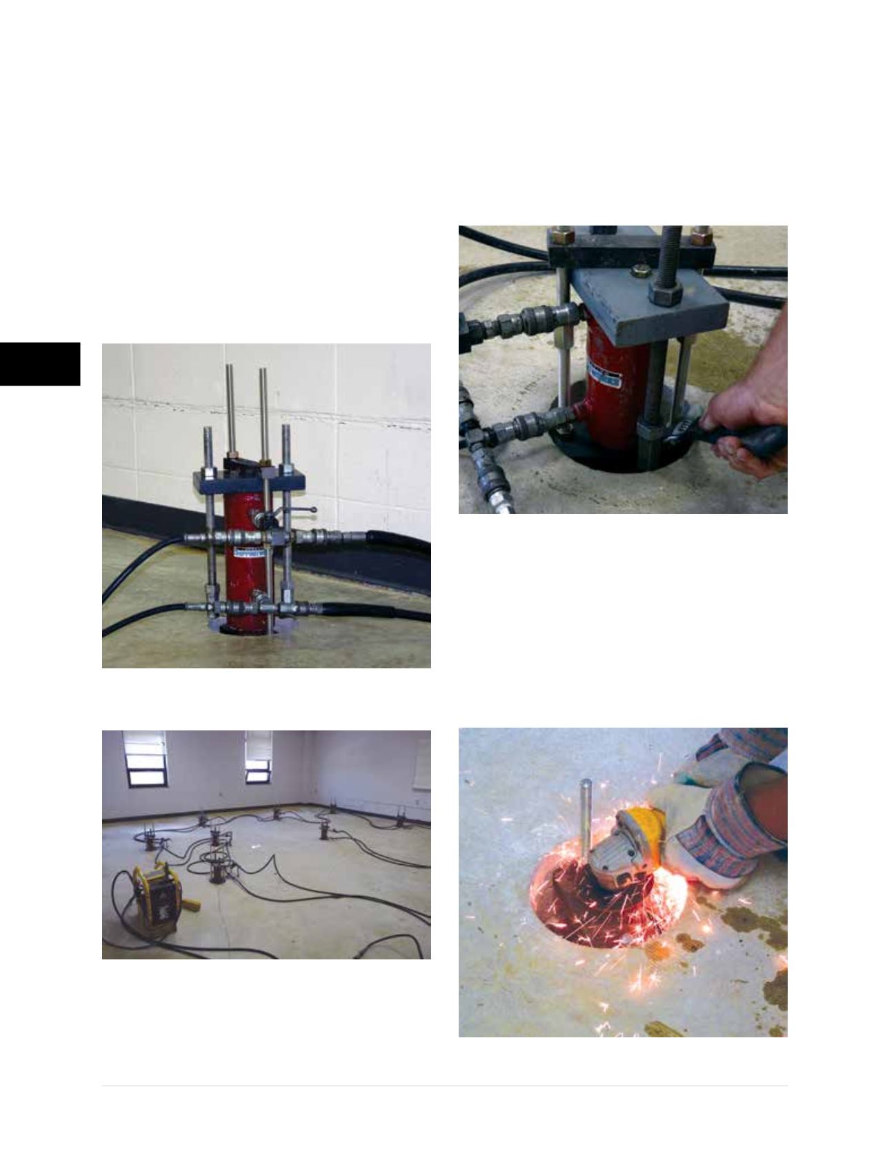
Figure 3.12.q
Hydraulic connections at lift cylinder
Figure 3.12.r
Lift cylinders in series
Figure 3.12.s
Pier load locked off by
tightening nuts on top of pier cap
Figure 3.12.t
Cutting the threaded rods