


 246 / 365

© 2014 Foundation Supportworks
®
,
Inc.
All Rights Reserved
p 246
Chapter 3
Hydraulically-Driven Push Piers
CHAPTER 3
HYDRAULICALLY-DRIVEN PUSH PIERS
spacing can be estimated using the Slab Pier
Spacing Guide of
Figure 3.12.b
. A grid pattern
spacing is provided for various slab thickness
and live load combinations. The guide also
considers unreinforced concrete slabs having a
minimum concrete strength of 2,500 psi.
Live Load
30
psf
40
psf
50
psf
60
psf
80
psf
Slab Thickness
3.5”
5’-0”
4’-6”
4’-3”
4’-0”
3’-9”
4.0”
5’-6”
5’-0”
4’-9”
4’-6”
4’-3”
4.5”
6’-0”
5’-6”
5’-3”
5’-0”
4’-6”
5.0”
6’-6”
6’-0”
5’-9”
5’-6”
5’-0”
6.0”
7’-3”
7’-0”
6’-6”
6’-3”
5’-9”
8.0”
8’-9”
8’-6”
8’-3”
7’-9”
7’-3”
Typical for Residential
Figure 3.12.b
Slab pier spacing guide
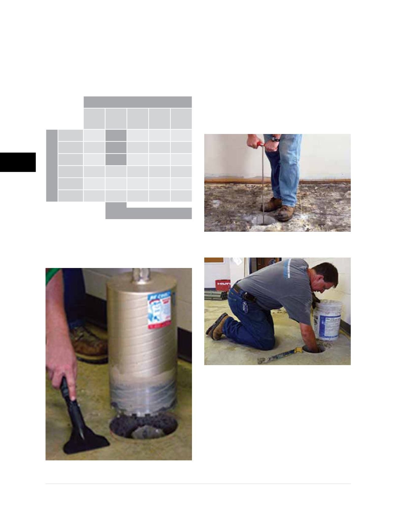
• Core 8-inch diameter holes in the concrete slab
(Figure 3.12.c)
. Adjust slab pier locations and
spacings based on the actual concrete thickness
determined at the first cored hole. Remove the
concrete cores and use a hand probe to check
for underground obstructions
(Figure 3.12.d)
.
Using a small hand tool, excavate all material
beneath the slab to at least 4 inches below
the bottom of the slab and extending at least
3 inches beyond the edges of the cored hole.
Check with your hand to confirm that the bottom
of slab is relatively smooth and free of subgrade
material
(Figure 3.12.e)
.
Safety precautions must be followed during
concrete coring to ensure the core drill
is securely mounted to the floor slab and
proper safety equipment including safety
glasses are worn during coring operations.
Immediately remove any water from the
floor when coring to reduce potential for
electrical shock. Keep body parts and other
objects away from core bit during operation.
Figure 3.12.c
Concrete coring
Figures 3.12.d
Probing for utilities or obstructions
Figure 3.12.e
Excavating beneath the slab