


 249 / 365

© 2014 Foundation Supportworks
®
,
Inc.
All Rights Reserved
p 249
Chapter 3
Hydraulically-Driven Push Piers
CHAPTER 3
HYDRAULICALLY-DRIVEN PUSH PIERS
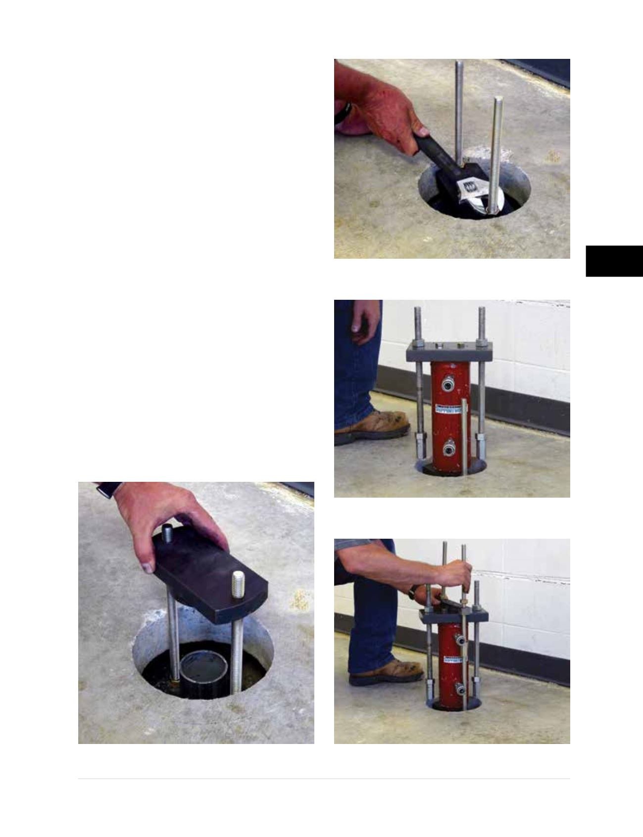
Step 5 Mounting the Lift Cylinder
• The last pier tube section is pulled from the
hole, cut to desired length in a chop saw and
replaced. The desired top of pier elevation
relative to the top of slab depends upon the
slab thickness and the maximum amount of
lift anticipated. If the slab will be stabilized
without lifting, the top of pier tube can be
approximately two inches below the top of
floor slab. It is imperative that the pier tube
is cut correctly to ensure that the pier cap,
threaded rod and nuts are below the top of the
slab after lift and/or lock-off operations.
• Place the pier cap over the threaded rods and
lightly tighten it against the top of the pier tube
with two
5/8
-inch hex nuts
(Figures 3.12.m and
3.12.n)
. Set the lift cylinder assembly onto the
pier cap
(Figure 3.12.o)
. Couple the threaded
rods of the lift cylinder plate assembly to
the threaded rods of the slab bracket to
hold the lift cylinder in place
(Figure 3.12.p)
.
Note:
The threaded rods of the lift cylinder
assembly are larger than the
5/8
-inch rods
of the slab pier bracket and are not used in
this application.
Figure 3.12.m
Pier tube cut
to length; pier cap placed
Figure 3.12.n
Lightly tighten
pier cap down onto pier tube
Figure 3.12.o
Lift cylinder
assembly set on pier cap
Figure 3.12.p
Lift plate assembly coupled
to threaded rods of slab pier bracket