


 247 / 365

© 2014 Foundation Supportworks
®
,
Inc.
All Rights Reserved
p 247
Chapter 3
Hydraulically-Driven Push Piers
CHAPTER 3
HYDRAULICALLY-DRIVEN PUSH PIERS
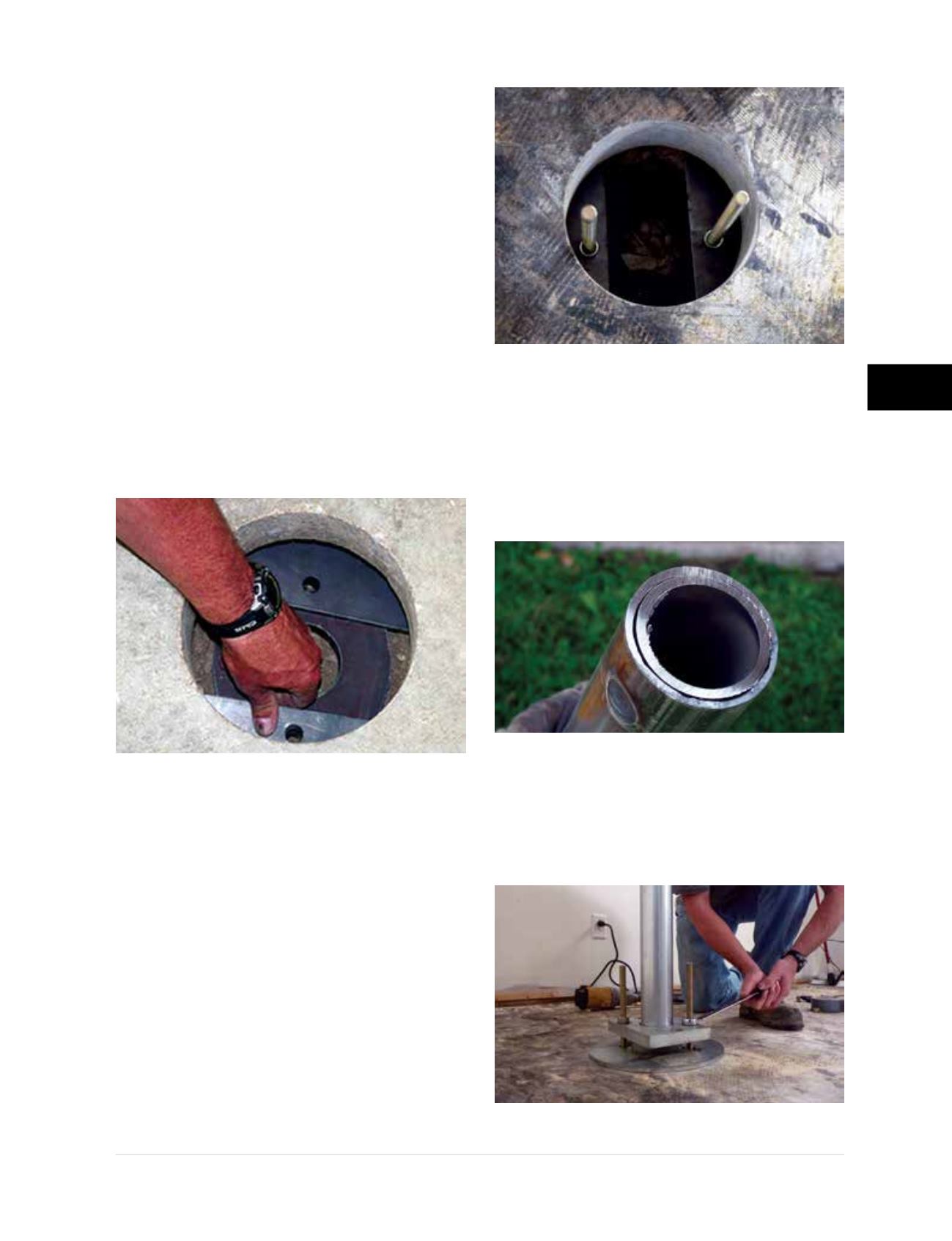
Step 2 Assembling the Bracket Below
the Slab
• The PP288 slab pier bracket assembly
consists of one (1) main plate, two (2) wing
plates, two (2) 14-inch long
5/8
-inch diameter
threaded rods, four (4)
5/8
-inch hex nuts and one
(1) pier cap. Set the main plate (first) and the
wing plates (second) through the cored hole.
Cover the welded nuts on the bottom of the
main plate with duct tape prior to placement
through the cored hole to ensure clean threads
for later insertion of the threaded rods. Locate
the wing plates above the main plate so that
the wing plate holes line up with the holes in
the main plate
(Figure 3.12.f)
. Align the straight
edges of the two wing plates to be essentially
parallel with each other.
• Install hex nuts on one end of the threaded
rods leaving about 2
½
inches of thread below
the nuts. Insert the threaded rods through
the wing plate holes and thread them into
the weld nuts below the main plate. Turn the
rods by hand until the nuts on the threaded
rods are seated against the top surface of the
wing plates. Continue to tighten the nuts with
a deep well socket to fasten the wing plates
firmly to the main plate
(Figure 3.12.g)
.
Step 3 Mounting the Drive Stand and
Drive Cylinder
• Cut the coupler extension off a standard
36-inch long pier tube to use as your starter
tube
(Figure 3.12.h)
. Insert the “coupler” end
of the starter tube through the hole of the
main plate. Place the slab pier drive adaptor
over the pier tube and fasten to the threaded
rods using two hex nuts
(Figure 3.12.i)
. Pull up
Figure 3.12.f
Main plate and wing plates
positioned and aligned beneath the slab
Figure 3.12.g
Threaded rods installed
Figure 3.12.h
Starter tube made by cutting
coupler end of standard pier tube
Figure 3.12.i
Slab pier drive adaptor installed