


 248 / 365

© 2014 Foundation Supportworks
®
,
Inc.
All Rights Reserved
p 248
Chapter 3
Hydraulically-Driven Push Piers
CHAPTER 3
HYDRAULICALLY-DRIVEN PUSH PIERS
on the threaded rods to bring the main plate
and wing plates against the bottom of slab.
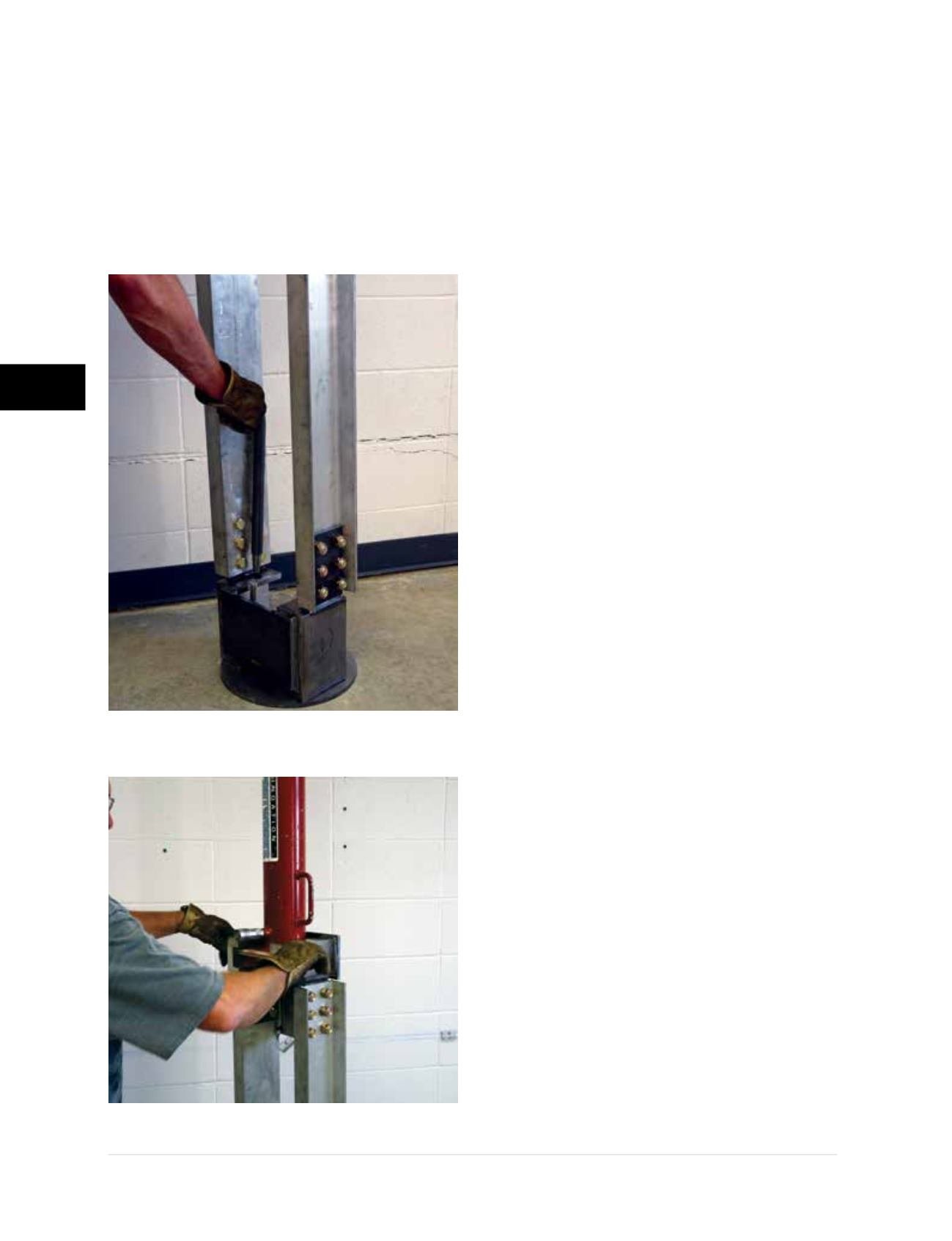
Slide the PP288 drive stand onto the slab pier
drive adaptor and secure with L-pins
(Figure
3.12.j)
. Set the hydraulic drive cylinder into
the top fixture of the drive stand and lock it
in position with the coil rod and nuts
(Figure
3.12.k)
. Connect the hydraulic hoses.
Step 4 Pier Tube Installation
• Electric pumps are preferred for slab pier
installations since the application of drive force is
moreeasily controlledand the riskof overstressing
the concrete slab during pier driving is reduced.
• Pier tubes are driven using similar procedures
as outlined in Section 3.10 (Step 4), including
recording of drive pressures at the end of each
driven tube. The drive stand should self-align
when force is applied by the drive cylinder to the
pier tubes; therefore, no cribbing or alignment
of the drive stand should be necessary if the
floor slab was prepared properly.
Safety precautions must be followed when
driving pier tube sections to ensure that
body and clothing are away from pinch
points. Take caution and avoid over-stroking
the cylinder rod which may result in a rapid
increase in pressure, possibly resulting in
cylinder damage or personal injury.
• Drive pier tubes until the required termination
drive force is achieved or slab movement
(flexing) in excess of about
¼
inch occurs. Care
should be taken by the installer to slowly release
hydraulic pressure at the end of each cylinder
stroke. Once the pre-determined termination
drive force is achieved or the slab starts to
lift, the pressure is released from the hydraulic
system and the drive stand and drive cylinder
are removed from the slab pier drive adaptor.
The drive adaptor is then disconnected from
the threaded rods of the slab pier bracket.
Figure 3.12.j
PP288 drive stand
mounted to slab pier drive adaptor
Figure 3.12.k
Drive cylinder set
into top fixture of drive stand