


 243 / 365

© 2014 Foundation Supportworks
®
,
Inc.
All Rights Reserved
p 243
Chapter 3
Hydraulically-Driven Push Piers
CHAPTER 3
HYDRAULICALLY-DRIVEN PUSH PIERS
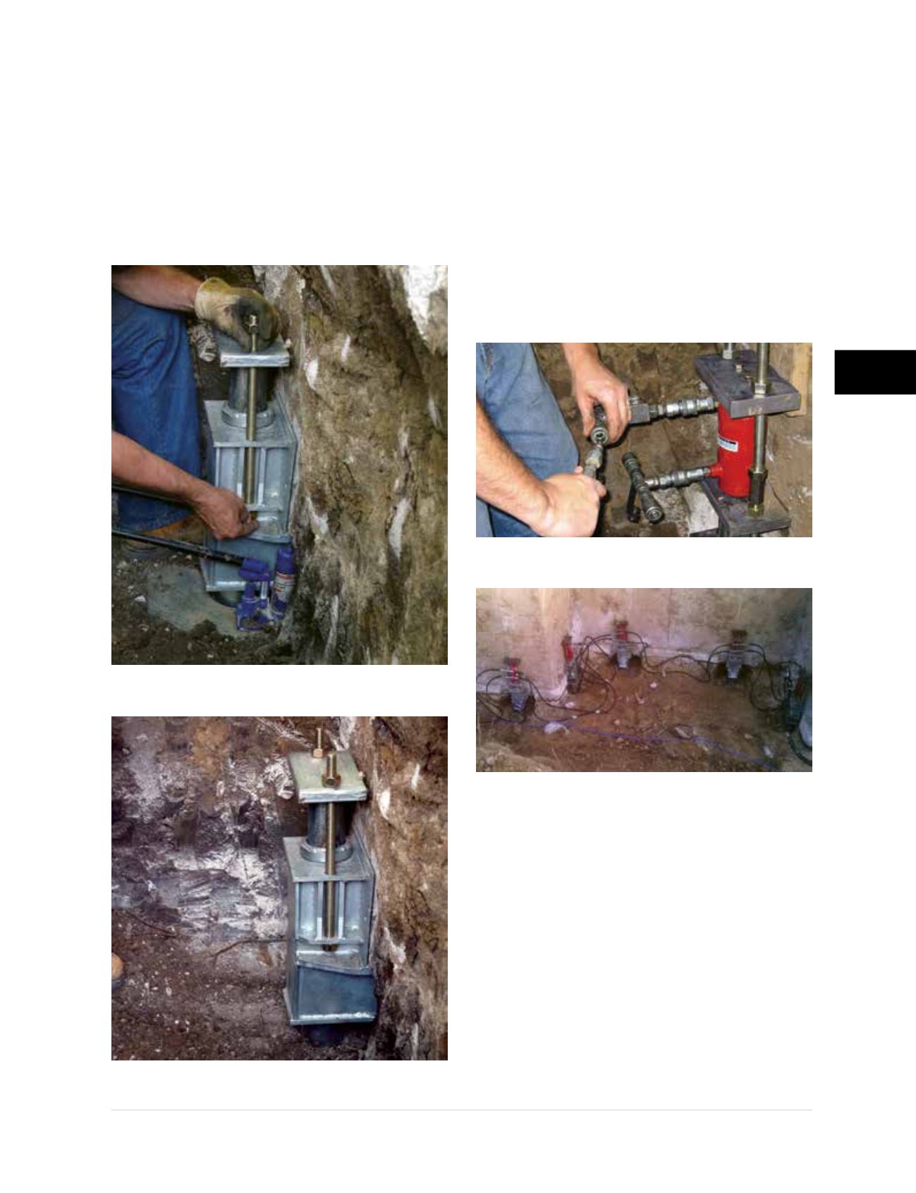
• The pier cap is set on the pier tube and two
threaded rods or coil rods are fed through the
holes of the pier cap and bracket. The pier cap
is connected to the bracket with nuts on each
end of the rods
(Figure 3.10.o1)
. There should
be adequate thread left above the top nuts
above the pier cap to allow coupling of the lift
cylinder assembly to the rods
(Figure 3.10.o2)
.
• Lift cylinder assembly rods are coupled
to the bracket assembly rods as shown in
Figure 3.10.p1
. Adjacent lift cylinders (piers)
are connected in series to provide uniform
application of load
(Figure 3.10.p2)
.
Note:
The hydraulic system shown in the figures
is technically a “parallel” system. However, it is
common to say that the piers are connected in
“series,” which simply means hydraulic lines run
between adjacent pier locations and they are
often all connected together with one set up.
Step 6 Structural Lift and/or Lock Off
• Hydraulic pressure is applied to the system to
either lift the structure to the proper elevation
or provide the required lock-off pressure/load.
The lock-off pressure/load is generally the
service load or design working load per pier.
It may be necessary to remove the soil from
above the footing if pocket excavations were
initially made. Removal of as much soil load as
possible around the foundation will increase
the potential to achieve a desired lift.
Figure 3.10.o1
Installation of pier cap
plate with threaded rods and nuts
Figure 3.10.o2
PP288 bracket
ready for lift cylinder assembly
Figure 3.10.p1
Connection of lift cylinder assembly
Figure 3.10.p2
Hydraulic system connected
to provide uniform application of load