


 245 / 365

© 2014 Foundation Supportworks
®
,
Inc.
All Rights Reserved
p 245
Chapter 3
Hydraulically-Driven Push Piers
CHAPTER 3
HYDRAULICALLY-DRIVEN PUSH PIERS
3.11 PP288 Flush-Mount
Push Pier Installation
The PP288 flush-mount bracket system may be
used for applications where poured concrete
elements such as a foundation wall, column,
pile cap or grade beam have adequate strength,
thickness and vertical dimensions to allow proper
attachment of the bracket. PP288 flush-mount
system capacities are provided in Appendix 3A
for systems using either expansion or adhesive
anchors.
Step 1 Concrete Preparation
• Excavation may be necessary to expose the
vertical face of the concrete. If the bracket
is mounted on a foundation wall or column
above a spread footing, the concrete footing
would have to be cored through or removed
entirely to allow for advancement of the pier
tube sections. The vertical face of the concrete
to receive the bracket should be smooth of
surface irregularities and free of structural
cracks. A thin layer of leveling compound
could be considered to create a smooth flat
surface prior to mounting the bracket.
Safety precautionsmust be followed prior to
and during excavation. Locate underground
utilities prior to excavation activities and
perform excavations at a distance away
from utilities as mandated by the utility
owner. Follow OSHA guidelines for trench
safety during excavation and installation
activities.
Step 2 Mounting the Bracket
• The flush-mount bracket is secured to the
concrete vertical face using eight (8) -inch
diameter anchors. Rather than attempting
to position and hold the bracket in place, a
template of the bracket bolt holes could be
considered to mark the anchor locations.
Steps 3 - 7
• The remaining steps for flush-mount push
pier installation are similar to those for the
under-footing system described in Section 3.10.
3.12 PP288 Slab Push Pier
Installation
The PP288 slab push pier system is used to lift
and/or stabilize settling concrete floor slabs.
Monometer survey equipment, a laser level, a
zip level, or other suitable equipment should be
used to identify low areas in the slab. Slab piers
should be located at these identified low points.
Slab piers should also be considered either
centered on or on alternating sides of significant
floor cracks to ensure an even lift. Voids beneath
a stabilized and lifted slab should be filled with
suitable material such as a cement grout or
PolyLEVEL
®
polyurethane foam.
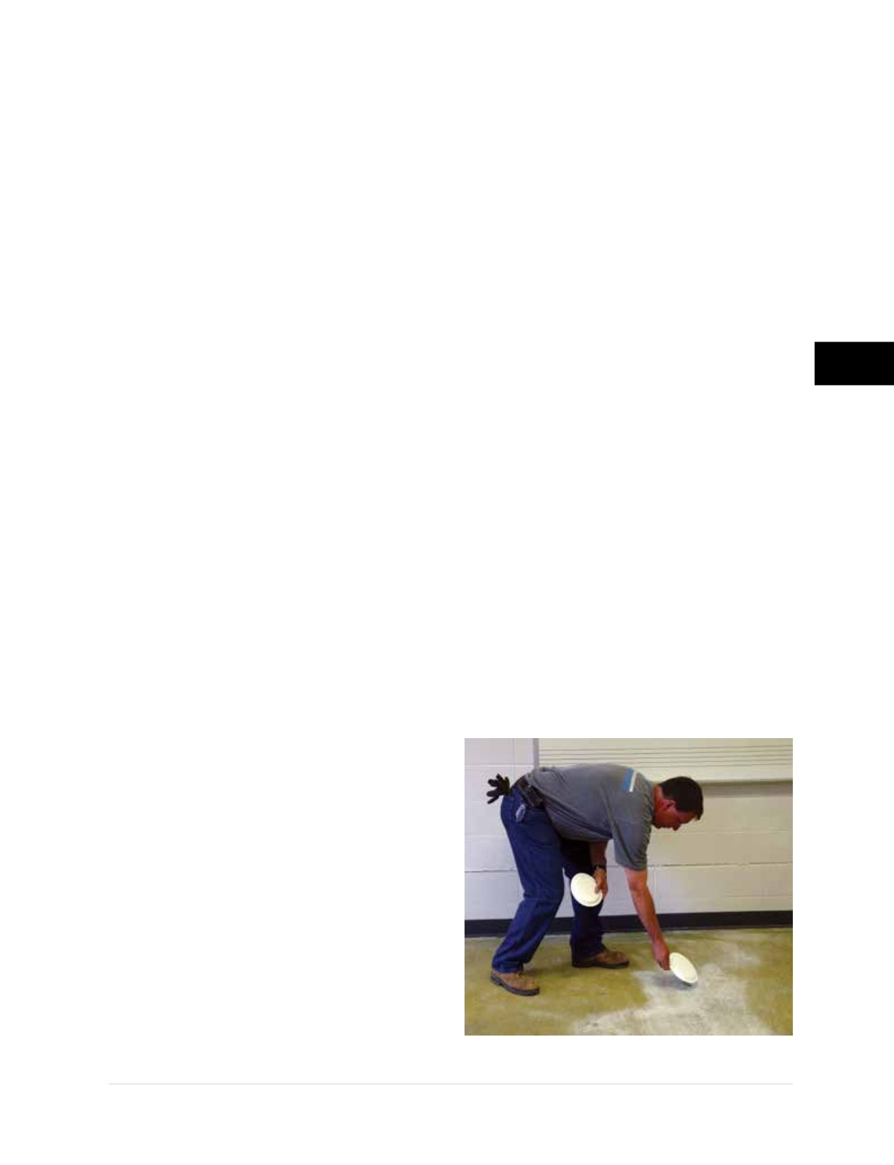
Step 1 Slab Preparation
• Mark the slab pier locations with consideration
to possible underground utilities, overhead
obstructions, maximum pier spacing, existing
floor cracks and lift requirements. Small paper
plates may be used to mark preliminary slab
pier locations since the plates can be easily
moved around the slab
(Figure 3.12.a)
. Slab pier
Figure 3.12.a
Marking slab pier locations