


 242 / 365

© 2014 Foundation Supportworks
®
,
Inc.
All Rights Reserved
p 242
Chapter 3
Hydraulically-Driven Push Piers
CHAPTER 3
HYDRAULICALLY-DRIVEN PUSH PIERS
of a driving tube tool. When the maximum
cylinder stroke has been reached, the cylinder
is retracted, the drive tube tool is set in place,
and the push is completed to the top of the
bracket or external sleeve
(Figure 3.10.k)
.
• Record the drive pressure at final stroke of
each pier tube section
(Figure 3.10.m)
.
Safety precautions must be followed when
driving pier tube sections to ensure that
body and clothing are away from pinch
points. Take caution and avoid over-stroking
the cylinder rod which may result in a rapid
increase in pressure, possibly resulting in
cylinder damage or personal injury.
• Once the pre-determined drive pressure is
achieved or the structure starts to lift, the
pressure is released from the hydraulic system
and the drive stand and drive cylinder are
removed from the bracket. The drive process is
repeated at each of the proposed pier locations.
Step 5 Assembling the Bracket and
Mounting Lift Cylinders
• The final pier tube extending up from the
bracket will often have to be cut to the desired
elevation. FSI push pier systems with an
external sleeve offer a tremendous benefit over
systems without external sleeves. The final
pier tube is protected from bending and the
high pinching forces common between short
brackets and push pier tubes. The final pier tube
is then easily removed from within the external
sleeve and placed in a chop saw to achieve
a square cut
(Figure 3.10.n)
. Alternatively, a
tube cutting guide can be positioned over the
in-place pier section and a cut can be made
with a reciprocating saw or portable band saw.
The last pier tube section is typically cut to a
length to extend above the external sleeve
approximately 4
½
inches. The cutoff length may
vary depending upon the amount of structural
lift anticipated. The removed pier section is
replaced after the cut is made.
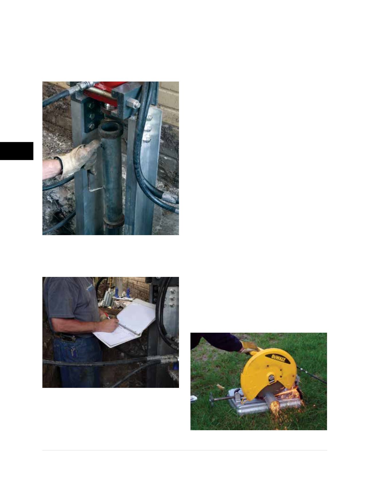
Figure 3.10.m
Pressure readings
are recorded for each pier tube
Figure 3.10.n
Cutting pier tube to
desired length with a chop saw
Figure 3.10.k
Driving tube tool set
in place for second stage of push