


 240 / 365

© 2014 Foundation Supportworks
®
,
Inc.
All Rights Reserved
p 240
Chapter 3
Hydraulically-Driven Push Piers
CHAPTER 3
HYDRAULICALLY-DRIVEN PUSH PIERS
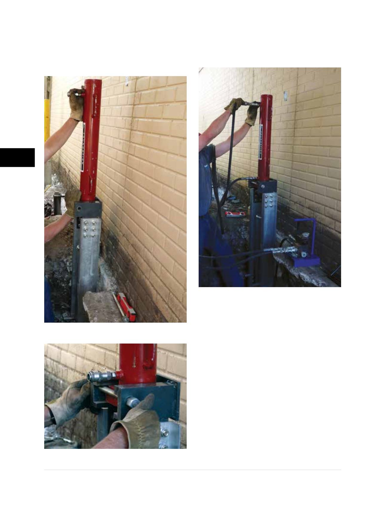
• Slide the hydraulic drive cylinder into the
top fixture of the drive stand and lock it in
position with the coil rod and nuts
(Figures
3.10.f1 and 3.10.f2)
.
• Connect the hydraulic hoses to the inlet and
outlet of the drive cylinder and the inlet and outlet
of the remote valve assembly
(Figure 3.10.g)
.
• Align the drive stand by activating the
hydraulics and extending the drive cylinder
rod to make slight contact with the starter tube
section. Use a digital level, protractor or other
device to check alignment of the drive stand,
sleeve, starter and bracket
(Figure 3.10.h)
.
Adjust the alignment as necessary for the
bracket system being utilized; i.e., 2-degree or
vertical brackets. Proper footing preparation is
critical for setting the bracket and system at the
correct installation angle. Temporary cribbing
may be used between the drive stand and the
foundation wall to set the correct installation
angle
(Figure 3.10.i)
while advancing the starter
tube and external sleeve.
Figure 3.10.f1
Hydraulic drive cylinder
placed within top fixture of drive stand
Figure 3.10.f2
Drive cylinder locked in
position with coil rod and nuts
Figure 3.10.g
Connect hydraulic hoses