


 241 / 365

© 2014 Foundation Supportworks
®
,
Inc.
All Rights Reserved
p 241
Chapter 3
Hydraulically-Driven Push Piers
CHAPTER 3
HYDRAULICALLY-DRIVEN PUSH PIERS
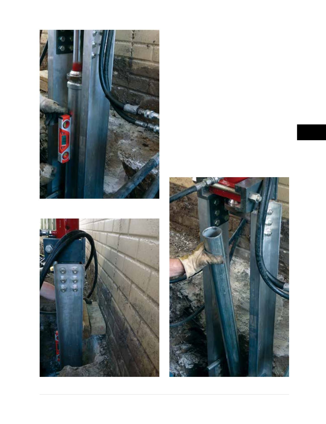
Step 4 Pier Tube Installation
• Drive the external sleeve and starter tube
together until the welded collar or trumpeted
end of the sleeve is seated at the top of the
bracket. Pier tubes are then coupled
(see
coupling detail in Figure 3.3.3.1.a)
and pushed
through the external sleeve
(Figure 3.10.j)
. The
standard length for pier tubes is 36 inches
for all of the FSI push pier systems. Drive
cylinders FS35DC and FS425DC have 22-inch
strokes. The PP237 and PP288 crawl-space
pier tubes have lengths of 18 inches and
are generally pushed with FSI drive cylinder
FS35CSDC, which has a 13-inch stroke. The
drive process for the sleeve and starter tube,
the standard 36-inch pier tubes, and the
18-inch crawl-space pier tubes therefore
requires a two stage process and the use
Figure 3.10.h
Checking drive stand
alignment with digital level
Figure 3.10.i
Temporary wood
cribbing used to set installation angle
Figure 3.10.j
Installing PP288 push pier tube